Introduction of Leroy-Somer Alternator R150 AVR
1 - GENERAL DESCRIPTION
The Automatic voltage regulator (AVR) is a compact, high performance encapsulated unit. The AVR incorporates latest technology and efficient semiconductor to achieve a high degree of miniaturization when applied to 3Ø and 1Ø AC brushless generator within its input and output limits, the unit offers excellent reliability.
The AVR supplies DC excitation to the exciter field of a brushless generator to keep the terminal voltage within close limits from NO-LOAD to FULL LOAD.
The recovery time on sudden loading is likely to be around 0.5 sec. to recover 98% of the rated voltage. Please note that the transient performance like voltage dip and recovery time are mainly decided by the generator and exciter design parameters. Best performance from the regulator can be obtained by keeping full load excitation around 60V DC.
The generator employs true average sensing circuit, dV/dt snubber and special filters circuits to cope with NON-LINEAR loading like battery charger, DC drives etc. The voltage regulation is guaranteed only for linear loading. Severely distorting NONLINEAR loads can cause regulation problem.
AVR is tested prior to dispatch through a quality plan, for standard voltage and frequency.
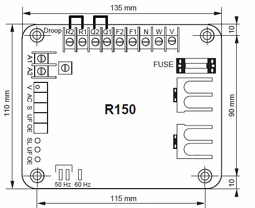
R 150 type AVR is provided with two accessory input terminals A1 & A2. Injecting ±4.5V DC in these terminals will change the generator voltage by ±10%.
Excitation power is derived from the main generator output winding.
Soft start circuitry is included which provides a smooth control on build up of generator output voltage.
A frequency roll off circuit continually monitors the generator, under speed protection by reducing the generator output voltage proportionally with speed below a threshold.
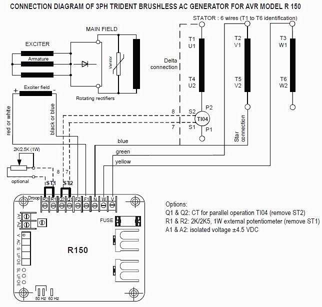
The AVR has the facility for droop CT connection, which is required for equal KVAR load sharing during parallel operation.

2 - OPERATION OF THE A.V.R.
The AVR derives its power supply from the line to neutral terminal of the AC Generator, at level of 277V AC rms at 50Hz or 60Hz. The sensing voltage, which is the regulated voltage, is derived from line to line (for 3 Ø) and line to neutral (for 1Ø). The AVR forms an important part of the close loop system comprising of the generator field, generator armature and the AVR.
The AVR first builds up the generator voltage from its residual levels. When the generator is loaded, the sensed voltage goes down and generates the error voltage, which is required to drive the closed loop system.
The AVR contains high gain amplifier, ramp and pedestal circuitry. Depending upon the value of the amplifier voltage (either high or low) the ramp intersects the amplified voltage at a point, which is early or late in the half cycle. At the intersection point a firing pulse is produced to trigger the power device.
When the power device is triggered early in the half cycle, more voltage is let into the field and when triggered late in the half cycle, less voltage is let in to the field.
In order to reduce the generator voltage at lower speed, a signal inversely proportional to the speed is fed as an extra input. At higher speeds the voltage reduces more than proportional with the speed.
R150 type AVR carries two additional terminals A1 & A2. These terminals could be used for accepting a DC control signal (isolated) from external controllers like APFC, Auto Synchronizer, etc.
It is important that the DC signal injected should be electrically isolated from the line terminals.
3 - TECHNICAL SPECIFICATION
1) Sensing input
- Voltage: 240 V AC ±10% for 1 phase, 380 V up to 480 V AC ±10% for 3 phase, 2 line sensing AVR Senses true average of the line to line waveform. Use Resistor (SMD) network for trouble free sensing & control of sensed voltage / regulation.
2) Input power
- Voltage: 415V for 3 phase and 240V for 1 phase
- Frequency: 50/60 Hz
3) Output power
- Voltage: 105 V DC at 240V AC Input
- Current:
• 6 Amps DC Continuous
• 8 Amps for 30sec. (when allowed by field resistance)
4) Operating temperature: -20ºC to +70ºC
5) Storage temperature: -40ºC to +80ºC
6) Voltage adjustment: min ± 10% of rated voltage.
7) Stability adjustment: adjustable to get Steady state Stability good transient response.
8) Remote Voltage adjustment: to get ±10% of set terminal voltage (with 2W / 2.5W , 1 Watt pot).
9) Droop for parallel operation: 4% droop for 5 Amps from «U» phase.
10) Auxiliary input A1 & A2: ±4.5V DC will give change in terminal voltage by ±10%.
11) Under frequency roll - off adjustment: available below 46 Hz for 50 Hz & below 56 Hz for 60 Hz.
12) Voltage Build up: ≥ 2 Volts (L-N)
13) Voltage regulation: ± 0.8% at AVR terminals.
14) Thermal drift: ± 1% for 30º C change in temperature.
15) Response time: less than 50 milli seconds.
16) Closed loop response: typically 0.5sec to recover to 98% of the set voltage for a field forcing ratio of 1:2.
17) Sense Loss protection: voltage should collapse, when the sensing circuit is open.
18) Over excitation protection: 10V DC to 85V DC. Set point : 60 V DC
19) Fuse for protection: 6 Amps, 240 Volts AC.
20) All potentiometers: multi-turn except Droop pot (Droop-single turn)
21) Sealing of Potentiometers: except V – trim pot all pots are sealed.
22) Frequency roll off indicator: LED provided (UF).
23) Sense Loss indicator: LED provided (SL).
24) Over excitation indicator: LED provided (OE).
25) Protection on the devices: Suitable R-C Snubber to be provided for the device used to protect this from surge.
26) Potting/ Encapsulation Details: the components on the AVR should be completely encapsulated with suitable PU resin compound to absorb transients / vibrations while in operation.
27) Excitation details of alternator: (typical)
- Full load:
• Excitation Voltage: 40 to 50 Volts
• Excitation Current: 2.5 to 5.0 Amps
28) Terminal marking: refer drawing
29) AVR Testing: Burn in test, Thermal cycling, Static test, Voltage variation check, Build up test, FRO check, Stability check, QDC check, Remote voltage check, DC input voltage check.
30) Dimension:
- Overall: 135 x 110 x 47.5 (in mm)
- Mounting: 115 x 90 (in mm)
- Mounting hole dia: 9 (in mm)
31) Weight: 320 gms
4 - MAIN FUNCTION OF THE A.V.R.
The AVR derives its power supply from line to neutral terminals of the ac generator at a level of 240V AC at 50/60Hz. The sensing voltage which is regulated is derived from the line to line terminals of the generator.

The AVR first builds up the generator voltage from its residual voltage to rated voltage.
When the generator is loaded, the sensed voltage goes down and generates the error signal, which is required to drive the closed loop system.
Depending upon the value of the amplified voltage, the ramp intersects the amplified voltage at the point which is early or late in the half cycle.
At the intersection point, a firing pulse is produced to trigger the power device.
Warning: Only qualified person should replace / operate on AVR. Do not increase the voltage beyond the rated voltage.
Comments