Characteristics of Leroy-Somer Alternator AVR R450
3.2.1.4 Excitation Limitation
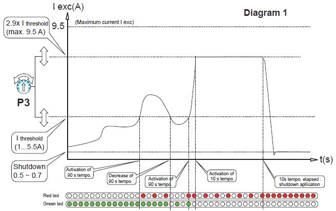
The limitation threshold must be adjustable between 1 and 5.5 A. The genset breaker must be open during the short circuit. If the genset is restarted in short circuit, there is a excitation build up during 10s again at the maximum value.
Operation between 3 and 6 In when short-circuited:
The excitation current ceiling during a short-circuit equals 2.9 times the fixed threshold when setting the permitted excitation ceiling in continuous operation.
When the threshold is exceeded for a period = 10 s the current is reduced to a value between 0.5 and 0.7 A (shutdown).
In all operating conditions the maximum excitation current must be limited to 9 A ± 0.5 A.
Overrun indications:
One green LED:
- Lights up when the excitation current is below the continuous operation threshold It signals the AVR normal operation.
- Turns off when the excitation current ceiling used to obtain short-circuit operation is reached and when the excitation current is reduced to the shutdown value.
- Flashes when the over excitation counter is decrementing.
NB: After an obvious short-circuit, the voltage is limited to 70% of the rated voltage. This avoids overvoltages on machines whose no-load excitation current is below the “lower current” threshold (only in AREP).
One red LED:
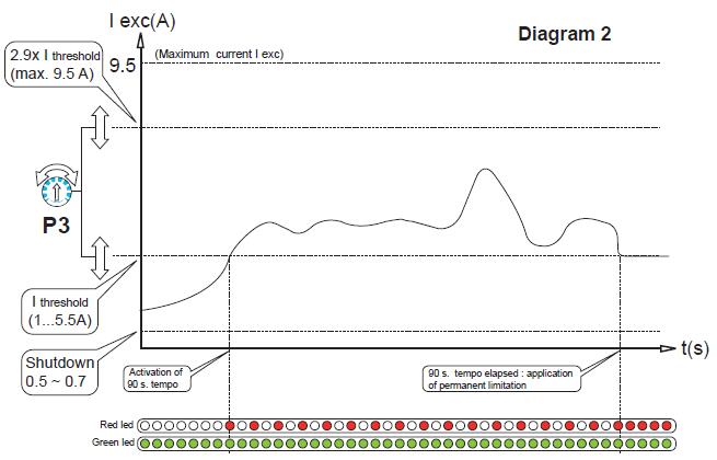
- Lights up simultaneously with the green led when the continuous operation threshold is reached for more than 90 s and the excitation current is reduced to the continuous operation threshold. It is used to set the excitation current ceiling
- Turns off when the excitation current is less than the setting value (< 110% In)
- Flashes when the excitation current is above the continuous operation threshold during less than 90 s.
Green LED stays on,
- flashes when the excitation current has reached the ceiling in < 10s with PMG excitation.
- ftays on if Iexc = I Shutdown.
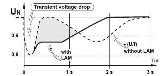
WARNING: If the overload protection is activated, a voltage drop possibly exceeding 10% of the reference voltage will be observed.
The AVR does not provide undervoltage protection. The customer will need to make sure that their installation is correctly protected against undervoltages.
During load shedding, an overvoltage is observed, which will disappear in a few seconds.
3.2.2 - Rotating switch selection: LAM and U/F
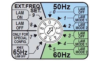
- Pos 0: Change in the voltage according to the U/F ratio, knee-point position at 48 Hz.
- Pos 1: Change in the voltage according to the 2U/F, knee-point position at 48 Hz.
- Pos 2: Change in the voltage according to the self auto-adaptating LAM combined with 2U/F, knee-point position at 48 Hz.
- Pos 3: Change in the voltage according to the U/F ratio, knee-point position at 58 Hz
- Pos 4: Change in the voltage according to the 2U/F, knee-point position at 58 Hz.
- Pos 5: Change in the voltage according to the self auto-adaptating LAM combined with 2U/F, knee-point position at 58 Hz.
- Pos 6: Change in the voltage according to the U/F ratio, knee-point position at 65 Hz (Tractelec application and variable speed above 1800 rpm).
- Pos 7: Special (not used).
- Pos 8: Change in the voltage according to the U/F ratio, knee-point position at 48 Hz or 58 Hz according to selection of the frequency by an external contact.
- Pos 9: Change in the voltage according to LAM 1, knee-point position at 48 Hz or 58 Hz according to selection of the frequency by an external contact
WARNING: For Pavers and hydraulic applications, select positions 0 (50 Hz) or 3 (60 Hz).
3.2.3 - Rotating switch: excitation type and time response
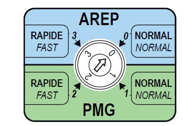
0: AREP excitation and normal time response.
3: AREP excitation and fast time response.
1: PMG excitation and normal time response.
2: PMG excitation and fast time response.
For SHUNT applications, AREP excitation must be selected.
3.2.4 - Rotating switch: voltage sensing
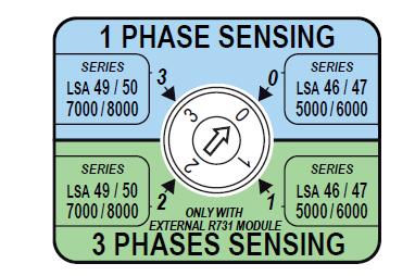
0: Single phase sensing
- LSA46 / 47 series.
3: Single phase sensing
- LSA49 / 50 series.
1: Three-phase sensing with optional module R731
- LSA46 / 47 series.
2: Three-phase sensing with optional module R731
- LSA49 / 50 series.
3.3 - U/F and LAM function
3.3.1 - Frequency variation compared with voltage (without LAM)
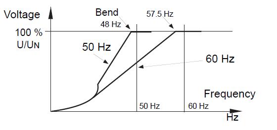
3.3.2 - LAM (Load Acceptance Module) characteristics
3.3.2.1 - Voltage drop
The LAM system is integrated in the AVR. As standard it is active.
Role of the LAM:
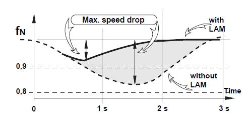
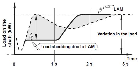
On application of a load, the genset rotation speed decreases. When it falls below the preset frequency threshold, the LAM causes the voltage to drop proportionately to the frequency (LAM1) or to the active power (LAM2) depending the the rotating switch position. This reduces the active load scale applied until the speed returns to its rated value.
Hence the LAM can be used either to reduce the speed variation (frequency) and its duration for a given applied load, or to increase the applied load possible for one speed variation (turbo-charged engine).
To avoid voltage oscillations, the trip threshold for the LAM function should be set approximately 2 Hz below the rated frequency.
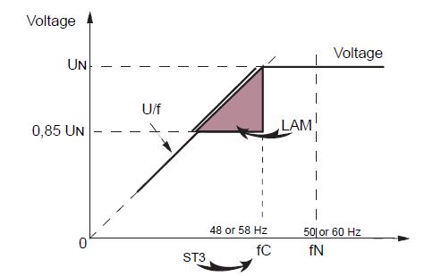
3.3.2.2 - Soft voltage recovery function
During load impacts, the function helps the genset to return to its rated speed faster with a gradual increase in voltage according to the principle:
- If the speed drops between 46 and 50 Hz (in 50Hz operation), the rated voltage is recovered by following a fast gradient.
- If the speed drops below 46 Hz, since the engine needs more help, the voltage follows a slow gradient as it returns to the reference value.
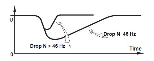
3.4 - Typical effects of the LAM with a diesel engine with or without a LAM (U/F only)
3.4.1 – Voltage
3.4.2 – Frequency
3.4.3 – Power
3.5 - AVR options
- Current transformer for parallel operation of....../1 A or 5 A according to the potentiometer P4 position.
- Voltage transformer (adaptation)
- Remote voltage adjustment potentiometer.
For a range of variation:
± 5% : 470 Ω
± 10% : 1 kΩ
the power of the potentiometer can be 0.5 W, 2 W or 3 W.
The potentiometer input must be isolated. Do not connect it to the ground.
- R731 module: 3-phase voltage sensing 200 to 500 V, compatible with parallel operation in balanced installations.
- R734 module: 3-phase current and voltage sensing for parallel operation on unbalanced installations (unbalance > 15%).
- R726 module: regulation system changed to “4 - function” (see the maintenance manual and connection diagram).
• PF regulation (2F) .
• Equalization of voltages before paralleling (3 F).
• Possibility of coupling to the mains of alternators already running in parallel (4F).
- R729 module: same as R726 with additional functions.
• Detection of a diode fault.
• 4-20 mA input.
• Possibility of kVAR regulation.
- Voltage control: with an isolated D.C. current source applied to the terminals used for the external potentiometer:
• Internal impedance 1.5 kΩ.
• A variation of ± 0.5 V corresponds to a voltage adjustment of ± 10%.


Comments